
The Mk 32 dual 5"/38 gun mount was the ship's secondary gun battery. It was capable of engaging both surface and airborne targets. The original Cleveland class ships had six dual 5 inch gun mounts. When the Oklahoma City was converted to a guided missile cruiser in the late 1950s all but one of the 5"/38 mounts were removed. The remaining mount #51 was moved forward from its original position to about where the #2 6"/47 turret had been. The superstructure and ammunition handling facilities were reconstructed around this new configuration.
The Mk 12 5"/38 gun and dual mount were designed in the early 1930s originally for destroyers, but it was so successful in its dual role that the 5"/38 was installed on all new destroyers, cruisers, battleships and aircraft carriers as the primary anti-aircraft weapon. It also served a secondary role for shore bombardment and engaging enemy surface ships. It is considered to be the most successful dual-purpose gun of World War II, and it continued to serve in the US Navy until the mid 1990s. The USS Long Beach CGN-9 had two single 5"/38 gun mounts when it was decommissioned in 1995.
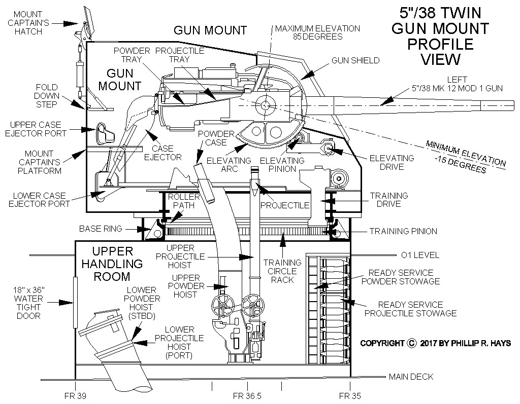
The Gun Mount rotated on a Base Ring on top of the Upper Handling Room. The base ring was circled by an armored barbette. Powder and projectile hoists for each gun carried ammunition from the Upper Handling Room to the mount. These hoists rotated with the mount. Lower fixed powder and projectile hoists brought ammunition up to the Upper Handling Room from the Lower Handling Room in the 5 inch projectile and powder magazines on the 2nd Platform Deck. About 90 rounds of ready service ammunition were stored in the upper handling room. This ammunition was available for immediate use during gunfire operations. The mount could fire up to 22 rounds per minute per gun from the ready service storage. After the ready service ammunition was expended the guns could operate at about 15 rounds per minute per gun using ammunition delivered from the lower projectile and powder magazines.
The mount normally operated under control of the Mk 1A computer in the Double Purpose Battery Plot Room. But it could be switched to Local Control if the automatic system failed to allow the mount crew to aim and fire the guns. In Automatic Mode the train and elevation were driven by hydraulic transmissions and the delay for Mechanical Time Fuzes was set as the projectile was ascending the projectile hoist to the mount, all under control of the Mk 1A computer. In Local Control the train and elevation hydraulic transmissions were controlled by the Trainer and Pointer's hand wheels. If the hydraulic system failed the Trainer and Pointer could switch to Manual Control where their hand wheels drove the training and elevation gear systems directly - but this method was very slow.
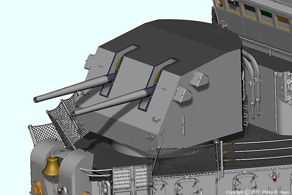
Mk 32 Gun Mount
The gun mount was enclosed in a lightly armored Mk 31 shield. The plating was 3/4 inch thick, enough to stop small caliber bullets and shrapnel from near misses, and it gave the mount crew some protection from the blasts of the guns, but it would not stop any large caliber projectiles or bombs. Shield weight was 31,400 pounds. This was the typical cruiser shield design. Shield thickness varied by ship type, from 1/4 inch on destroyers to 2 1/2 inch on battleships. Total Mk 32 mount weight was about 118,000 pounds.
The mount carriage rested on conical roller bearings that traveled on a Roller Path on the Base Ring. The Base Ring also had a Training Rack internally toothed gear that circled the inside of the ring. The Training Pinion gear was driven by a hydraulic transmission in the mount and rotated in the Training Rack to turn the mount. The maximum training arc was ±130° to port or starboard. The superstructure was angled to give clear firing for the mount. The mount rotated at 25° per second, and the guns elevated at 15° per second. These rates were high enough to track fast moving aircraft targets. The guns were driven by an Elevating Arc on the bottom of each gun. This was powered by a hydraulic transmission. Gun elevation ranged from -15° to +85°. Maximum range was 17,392 yards (8.6 nautical miles) at a gun elevation of 45° with an AA Common round. Maximum height was 37,200 feet.
The Gun Mount had a normal crew of 13 men, with another couple dozen in the Upper and Lower Handling Rooms and magazines. The Mount Captain stood on a platform at the rear. A hatch over his position allowed him to look out over the mount to observe fire, but this wasn't used on the Oklahoma City after missile conversion because for much of the ship's life a base for a whip antenna on top of the mount obscured the view. The Mount Captain's responsibility was to supervise the mount crew and the Upper Handling Room crew so the gun could operate with an effective rate of fire, and to report the mount status to Gun Plot. During training exercises the Checker was responsible for training mount personnel in the proper use of their equipment and for observing the fall of shot. He used a telescopic sight that protruded to a hooded port on the left side of the mount behind and above the Pointer's telescope to check that the guns were aiming at the target. The Checker position was manned only during training.
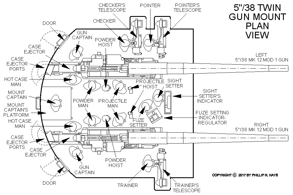
Each gun had a Gun Captain, Powder Man, a Projectile Man and a Hot Case Man. The Gun Captain was responsible for keeping the gun operating. The Powder Man removed the powder case from the powder hoist, removed a protector from the fuze, and put the powder in the loading tray on the gun. The Projectile Man took the projectile from the projectile hoist and put it in the gun's loading tray. Then he operated the rammer mechanism that pushed the projectile and powder case into the gun. The Hot Case Man was responsible for seeing the spent powder cases were removed from the gun after the gun fired and ejected from the mount. At gun elevations below 40° the shell cases fell into the case ejector chute and exited the mount through the Lower Case Ejector Port. At angles above 40° the case ejector did not work so the Hot Case Man grabbed the spent shell case and pushed it out the Upper Case Ejector Port.
Note: OP 805 1 Mentions a Shell Guard Man for each gun that operated the shell guard. After the gun fired and recoiled the shell guard was in a raised position the Shell Guard Man lowered it into place for loading the next round. He also operated the breech block hand operating lever. It is not clear to me that there really was a Shell Guard Man in the mount. Most sources do not mention him and say the Gun Captain operated the manual breech lever.
The Pointer and Trainer could aim the guns manually in Local Control. The Pointer sat at the left front of the mount. He controlled the elevation of the guns and had a trigger to fire the guns electrically. He also had a foot operated lever to cause the mechanical firing pin in the breech block to fire the round by percussion. The Pointer had a telescopic sight with cross hairs that extended to a hooded port on the side of the mount to allow him to observe the target and align the guns on it. The Trainer sat at the front right corner of the mount and controlled the mount's bearing. He had a telescopic sight with cross hairs that extended to a hooded port on the side of the mount to allow him to point the guns at the target.
The Sight Setter's position was between the guns forward of the projectile hoists. He adjusted the sights in the mount to correct for range to the target, target motion, parallax between the mount and the Director and gun elevation to keep the Pointer, Trainer and Checker's cross hairs aligned on the target. The Fuze Setter was between the guns behind the Sight Setter. He operated the fuze setting equipment that adjusted the timing of mechanical time fuzes. In Automatic Control the fuze setting equipment in the Upper Powder Hoists was controlled by the Mk 1A Computer in Gun Plot. In Local Control the Fuze Setter entered the time delay manually into the fuze setter controls.
The mount had a firing stop mechanism that rode on a specially machined cam. If the mount rotated to a position where gunfire might strike the ship the cam mechanism interrupted the firing mechanism.
Upper Handling Room
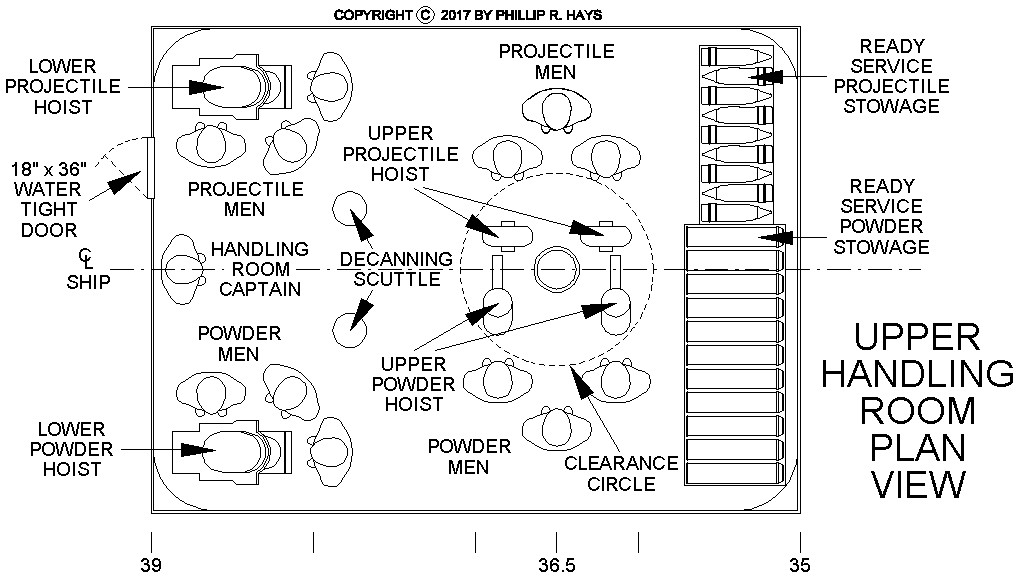
The Upper Handling Room had a crew of 13 men. The Handling Room Captain supervised the handling crew and was responsible to the Mount Captain for maintaining a constant flow of ammunition to the mount. There were six Projectile Men. Two operated the upper end of the Lower Projectile Hoist to bring shells up from the magazine. Two carried projectiles from the ready service projectile storage or from the Lower Projectile Hoist to the Upper Projectile Hoists. Two men placed projectiles into the Upper Projectile Hoists and operated the hoist mechanisms.
There were six Powder Men. Two operated the upper end of the Lower Powder Hoist that brought powder cases up from the magazine. Two Powder Men carried powder cases from the ready service powder storage or from the operators of the Lower Powder Hoist to the Upper Powder Hoists. Two men loaded powder cases into the Upper Powder Hoists and operated the hoists.
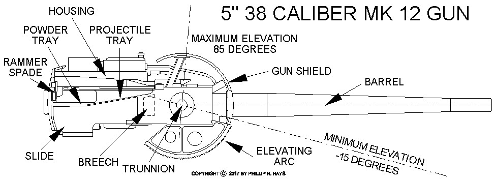
5 Inch 38 Caliber Mark 12 Mod 1 Gun
The major parts of the gun assembly were the barrel, housing, breech, gas ejector and slide. Naval gun calibers are specified in bore diameters. The bore diameter was 5 inches, so the length of the barrel from the breech block to the muzzle was 38 x 5 = 190 inches, or 15 feet 10 inches. Weight of the gun assembly was 13,850 pounds. The left and right guns were mirror images of each other, with the loading trays on the sides closest to the center of the mount. Overall length of the gun assembly was 243.75 inches and they were 21.94 inches wide.
The barrel was a single radially expanded monoblok casting that was rifled with a twist of 1 turn in 30 calibers (150 inches). The rifling had 45 grooves that extended about 13 feet from the end of the powder chamber to the muzzle. The inside of the barrel was chrome plated from the muzzle about 13.5 feet into the powder chamber. The barrel weighed 3995 pounds and attached to the housing with a rotate to lock interrupted thread bayonet fitting. A key locked the barrel in place. The barrel could be removed and replaced without disassembling the gun assembly. Average barrel life was about 4600 rounds. Maximum chamber pressure during firing was 18 tons per square inch. Full charge muzzle velocity was about 2500 feet per second. Reduced charge muzzle velocity was 1200 feet per second.
The gun housing was a rectangular forging that contained the breechblock, recoil and counterrecoil mechanisms and the gas ejector system. The forward end of the housing had a bayonet receptacle that attached to the breech end of the barrel and the housing supported the barrel. A machined vertical well housed the breech block. The ammunition tray was aft of the breech block. Two recoil cylinders and one counterrecoil cylinder were in the housing. Each side of the housing had a slot to engage a bearing surface on the slide. When the gun fired the housing and barrel recoiled 15 inches in the slide. The weight of the recoiling barrel and housing assembly was 8150 pounds.
The breechblock was a vertical sliding wedge type that fit into a well in the housing. It lowered into the housing to allow ammunition to be loaded into the gun and then raised to a locked position for firing. As it rose it moved forward to wedge the powder case tight against the barrel. It contained the electrical and mechanical firing mechanisms that detonated the primer in the powder cases. Powder case extractors rode on the breechblock. Cam action as the breechblock descended caused the extractors to pull the spent powder case from the gun barrel. The breechblock was normally lowered and raised automatically, but a hand lever allowed it to be operated manually.
The firing mechanism in the breechblock contained a pin that contacted the primer in the center of the end of the powder case. The combination primer was normally fired electrically, but if this failed a spring loaded firing plunger could be released to drive the pin into the primer cap. The plunger was cocked when the breechblock opened.
The slide was an open top and bottom box that contained the gun housing and barrel assembly. It had slide rails for the gun housing to move on and a roller bearing at the front to support the barrel. The rammer mechanism was attached to the slide. The slide pivoted around the horizontal axis on trunnions that rode in trunnion bearings in the gun carriages. The slide moved the rest of the gun mechanism through elevation. An Elevating Arc gear on the bottom of the slide was driven by a worm gear powered by the elevation gear hydraulic transmission.
Two recoil cylinders in the gun housing absorbed the recoil energy of the firing gun. The recoil pistons were attached to the slide and did not move. As the housing recoiled fluid flowed from one side of the pistons to the other through small channels in the housing, thereby restricting the rate of movement of the housing and barrel. During counter recoil the same mechanism controlled the return of the housing and barrel to the ready position.
The counterrecoil mechanism had a piston fixed to the slide that fit into a cylinder in the gun housing. Air the the chamber was compressed when the gun recoiled. After recoil this air pressure forced the housing and barrel back into the ready position.
During counterrecoil pressurized air was blown into the firing chamber to blow unburned powder and gasses out the muzzle of the barrel. The gas ejector system prevented unburned gasses from causing flashback in the gun mount that might burn the gun crew, start a fire or cause ammunition in the mount to explode. The air ejector system could also be operated manually.
Ammunition

There were at least sixteen types of projectiles for the 5"/38 guns and three powder types. The common burster charge in the projectiles was Explosive D (Ammonium Picrate) that had a velocity of detonation of 21,300 feet per second. It was less sensitive to shock than other explosives and was safer to handle, but some nose fuzes did not reliably detonate Explosive D. Auxiliary Fuzes were placed between the nose fuzes and the burster charge to boost the detonation. Some anti-aircraft rounds carried explosive charges of Composition A (91% RDX in wax) that had a velocity of detonation of 27,000 feet per second. It produced a more powerful explosion than Explosive D so it was more desirable for the smaller bursting charges in Variable Time Fuzed AA rounds. Most rounds were pretty insensitive to dropping, but the Smoke (white phosphorous) and Rocket Assisted Projectile (RAP) rounds had to be handled with caution.
The Common and Special Common projectiles were light armor piercing rounds. The special hardened tempered steel cases had blunt noses to allow them to penetrate armor plate over a wide range of impact angles without ricocheting. Common rounds could penetrate up to 1 2/3 inches of hardened armor plate. The Special Common rounds had an additional hardened hood over the nose to allow penetration of up to 2 1/2 inch thick armor plate. Upon impacting armor plate the hood caused the initial stress on the armor and deformed to flow around the main armor piercing body. The main body penetrated into the armor plate. After a delay sufficient for the projectile to penetrate the armor the explosive charge was detonated to expand the hole in the armor and spread fire and shrapnel inside the target. The windshield was a thin metal ogive attached to the front of the projectile to decrease drag from air friction and extend the range of the projectile.
The Anti-aircraft (AA) Common rounds contained a large burster charge that scattered shrapnel when they exploded. When used against aircraft they carried a Mechanical Time Fuze or Variable Time Fuze in the nose. These rounds could also be used as High Capacity (HC) rounds against unarmored surface targets. For this use they carried a Base Fuze for immediate explosion on contact and either a Point Detonating Fuze, Mechanical Time Fuze or Variable Time Fuze in the nose. The time delay fuzes could be used to detonate the round in the air above the ground to scatter shrapnel over the target area. The Variable Time Fuzes were larger than other nose fuzes and required a larger cavity in the explosive charge - and less explosive. The cavity was normally lined with a thin aluminum case to avoid friction between the explosive charge and the VT fuze - these were called Fuze Cavity Lined (FCL-VT) projectiles.
Some VT rounds were loaded with just a very small exploding charge to prevent bursting the shell and scattering shrapnel. These FCL-VT-NF rounds were used in target practice against expensive drone targets to reduce the probability of destroying the drone. The nose fuze or base plug was blown out producing a puff of smoke for spotting. They contained fillers of epsom salts or other inert filler to give the projectile the desired weight. Additional color burst fillers could be added behind the VT fuze to color the smoke.
Illumination rounds were fired high in the air above targets. A Mechanical Time Fuze detonated a small charge to push the Mk 4 Mod 5 Illumination Package flare and parachute out of the base of the projectile. The flare descended under the parachute. The flare is said to have burned for 50 seconds, but I have found no technical description with a definite burn time.
The Window or "chaff" projectiles scattered a cloud of aluminum foil strips in the air. The foil reflected radar signals making it impossible for enemy radars to see through the chaff cloud. But more importantly, the chaff created a large false target for enemy missiles to home on. When a lookout or radar operator sighted an incoming enemy missile he shouted "Zombie! Zombie!" and the bearing of the target into the ship's internal communications system. The 5"/38 Mount immediately swung to the opposite bearing and fired several chaff rounds into the air on the opposite side of the ship from the missile. This created a large false target beyond and above the ship, confusing the missile and causing it (hopefully) to fly over the ship and home on the chaff. Then the Mount swung back around to engage the missile with anti-aircraft rounds. There were three different chaff loads, each designed to interfere with specific radar frequency bands.
Mk 1, Mk 2, Mk 3 and Mk 4 training rounds or Drill Projectiles were ordinary projectiles loaded with an inert filler (sand?) and no fuzes. They were Blind Loaded and Plugged (BL&P) without a tracer and Blind Loaded and Tracer (BL&T) with a tracer. The Mk 6 Dummy Drill projectile was manufactured specifically as a training round.
The Mk 32 Common projectile was 20.7 inches long with a windshield, or 13.6 inches without the windshield. It weighed 54 pounds and carried 2.58 pounds of explosive D. It was the basic armor piercing round and used the Mk 20 Base Fuze with a 0.01 second delay. It could carry the Mk 9 tracer. It was also issued as BL&P and BL&T training rounds with 2.58 pounds of inert filler and the Mk 9 tracer.
The Mk 38 Special Common projectile was 20.7" long and weighed 55.18 pounds. It contained 2.04 pounds of explosive D. It was similar to the Mk 32 but had an armored hood over the nose. It used the Mk 20 base fuze and the Mk 9 Tracer.
The Mk 46 Special Common shell was 20.7 inches long with windshield or 12.5 inches without the windshiels, and had a hood over the nose of the body. Weight of the projectile was 55.18 pounds with a 2.04 pound explosive D bursting charge. It used the Mk 20 Base fuze and the Mk 9 tracer. It contained a spotting dye in the windshield.
Mk 31 AA Common was strictly an anti-aircraft round intended to be used with the Variable Time nose fuze. It was 20.7 inches long and weighed 55.12 pounds. The projectile contained 7.25 pounds of Explosive D or Composition A. The base was plugged and it did not use a tracer or base fuze. It used the Mk 58 Variable Time Fuze boosted by the auxiliary fuzes Mk 17, Mk 44, Mk 46 or Mk 54. The Mk 31 was also issued as BL&P and BL&T training rounds with 7.25 pounds of inert filler and an adapter for the a tracer.
Mk 34 AA Common was a dual purpose round used primarily for anti-aircraft use with a Variable Time Fuze or Mechanical Time Fuze, but also as a High Capacity round with a Point Detonating Fuze. It was 20.7 inches long, weighed 55.18 pounds and carried 7.26 pounds of Explosive D or Composition A as an AA round and 13.2 pounds as a HC round. It was used with noze fuzes Mk 50 and Mk 63 Mechanical Time Fuzes, Mk 29 Point Detonating Fuze and Mk 40 Variable Time Fuze (obsolete) and the auxiliary fuze Mk 54. The Mk 34 was a modified Mk 31 Mod 10 projectile to use Mk 28 base fuze and Mk 9 tracer, however these were not used with the Mk 40 nose fuze. The Mk 40 VT fuze was large and not especially reliable so the Mk 34 round probably saw service for only a short period.
The Mk 35 AA Common with a Mechanical Time Fuze or Variable Time Fuze was used primarily for aircraft targets. With a Point Detonating Fuze it was considered a conventional High Capacity (HC) round. It was 20.7 inches long with a nose fuze and 17.2 inches without. It weighed 55.18 pounds and carried 7.55 pounds of Explosive D with the mechanical time fuze. With the FCL-VT fuze it had 7.86 pounds of Explosive D or Composition A explosive. The FCL-VT-NF version carried about a pound of Composition A. Nose fuzes Mk 50 and Mk 60 Mechanical Time Fuzes, Mk 29 Point Detonating Fuze and Mk 53 Variable Time Fuze could be used. Auxiliary fuzes Mk 44 and Mk 54 were used with the nose fuzes. With 1200 foot per second muzzle velocity Mk 5 reduced charge powder cases the nose fuzes Mk 61 and Mk 29 were used with the Mk 54 auxiliary fuze. No base fuze or tracer were used with the Mk 53 VTF. With other nose fuzes the Mk 28 base fuze and Mk 9 tracer could be used. The Mk 35 could be loaded as a Mk 4 Dummy Drill Projectile training round with a nose plug and configured as BL&P with a base fuze plug or BL&T with the Mk 9 tracer and 7.55 pounds of inert filler.
Mk 47 AA Common was 20.7 inches long with a nose fuze. It weighed 55.18 pounds and carried 7.82 pounds of Composition A. It could carry nose fuzes Mk 50 and Mk 60 Mechanical Time Fuzes, Mk 29 Point Detonation Fuzeand the Mk 53 Variable Time Fuze (FCL-VT), with auxiliary fuzes Mk 44 and Mk 54. Base fuze Mk 28 and the Mk 9 tracer could be installed, but were not used with the Mk 53 VTF. It was designed for newer lighter nose fuzes but in service it was fuzed just like the Mk 35 projectile. Only a few thousand Mk 47s were made and it saw little action.
The AA Common Mk 49, MK 52 and Mk 56 all weighed 55.2 pounds and carried 7.55 pounds of Explosive D except Mk 52 with 8.4 pounds of RDX/Wax 91/9 composition A3. Mk 49 was also loaded as BL&P and BL&T training rounds.
The Mk 30 Illuminating projectile was 20 inches long and weighed 54.5 pounds. It had 2.5 ounces of black powder to eject the Mk 4 Mod 5 illuminating contents. The case had a base plug that was easily blown out by the ejection charge. It was used with nose Mechanical Time Fuzes Mk 50 and Mk 63. The Mk 30 case was used for a variety of projectile types.
The Mk 44 Illuminating round was 20 inches long with nose fuze. It weighed 54.5 pounds and used 2.5 ounces of black powder to eject the Mk 4 Mod 5 illuminating contents. The Mk 50 and Mk 63 Mechanical Time Fuzes were used with the Mk 44 round. The Mk 44 case was also used for Window (chaff)and Smoke (White Phosphorous) rounds.
The Mk 45 Illumination round weighed 54.4 pounds and carried a 2.5 ounce ejection charge. It used the Mk 4 Mod 5 Illuminating Contents.
The Mk 78 Window (chaff) round used the Mk 30 projectile body. Length was 20 inches and it carried 2.5 ounces black powder to eject the chaff package. It could use three different chaff loads. The Mk 1 Mod 1 Window load contained 13,800 8 inch long x 3/16 inch wide aluminum foil strips. The Mk 2 Mod 0 Window load had 19 rolls of aluminum foil each 600 feet long by 1/2 inch wide. The Mk 4 Mod 0 Window load had two stacks of 13,800 aluminum foil strips 5.1 inches long x 3/16 inch wide. Weight with the Mk 1 Mod 1 load was 53.9 pounds, with the Mk 2 Mod 0 load it weighed 54.6 pounds, and with the Mk 4 Mod 0 load it weighed 53 pounds. Mechanical Time Fuze nose fuzes Mk 50 and Mk 63 were used.
The Mk 46 Smoke (White Phosphorous) round used the Mk 30 projectile body. Length was 20 inches and it weighed 53 pounds with 4 ounces of black powder to ignite the white phosphorous load. Nose fuzes Mk 50 and Mk 63 Mechanical Time Fuzes, Mk 29 and Mk 66 Point Detonation Fuzes were used with the full Mk 5 powder case, and the Mk 61 Mechanical Time Fuze was used with the 1200 foot per second Mk 5 Reduced Charge powder case. The white phosphorous canister was 12 inches long x 3.9 inches diameter with a 14 gram ballistite burster charge down the center and a black powder delay at the upper end. It contained four sections of 42 each 2.86 inch long x 0.5 inch diameter steel tubes filled with white phosphorous - 168 tubes total. The canister was filled through the base with molten white phosphorous giving it 7.06 pounds of white phosphorous total. The expelling charge ignited the delay element and forced off the base plate, ejecting the WP canister. The delay triggered the burster charge that scattered the WP tubes after the canister had exited the Mk 30 projectile body. A smoke cloud 30-40 yards diameter was created. It was used for smoke screening, anti-personnel and incendiary purposes. "Willy Peter" was often used as a spotting round because the large white smoke cloud was easier to see than a regular exploding round, especially in the dense jungles of Viet Nam.
The Mk 57 Rocket Assisted Projectile (RAP) was developed in the 1960s as a way to extend the range of guns with a small rocket motor in the projectile. It was used against enemy personnel and unarmored shore targets and enemy shipping. I have found only limited information about the projectile. It is said to weigh 54.3 pounds and carried 3.5 pounds of Explosive D. One source said it was 51.5 inches long, but this is ridiculous - that is longer than the combined length of an ordinary round and a Mk 5 powder case and wouldn't fit into a 5"/38 gun. It was more likely 51.5 centimeters, which is 20.276 inches long, about like the other 5"/38 rounds. Range is said to have been 23,770 yards or 11.7 nautical miles, which is 140% of the maximum range with AA Common rounds. An internal percussion cap primer in the Mk 279 Igniter was triggered when the projectile accelarated down the gun barrel. It started a time fuze that burned 23 seconds until the round was some distance from the ship. Then the igniter lighted the rocket motor which burned 1.6 seconds. The igniter was blown out through the nozzle upon ignition of the rocket motor. The rocket propellant was an extruded plastic explosive that could withstand the shock, centrifugal forces and high acceleration forces when the powder charge fired the round from the gun. It used a Point Detonating Fuze or a Variable Time Fuze. The round could be triggered by dropping it on the base against a sharp point, initiating the time delay igniter, making it more dangerous to handle than other 5 inch projectiles. The Oklahoma City fired 275 5 inch RAP rounds in Viet Nam. They were inaccurate and not very useful against point targets. They were later discontinued.
The Mk 20 Base Detonating Fuze was used with Common and Special Common rounds, and could carry the tracer. It was armed by setback and centrifugal force. It would detonate on contact with 3/4 inch plate at angles up to 80° and water, with a 0.01 second delay.
The Mk 28 Base Detonating Fuze was used with AA Common rounds. It would detonate on 1/4 to 1/2 inch plate at all likely angles and in water with 0.003 second delay. It was armed by setback and centrifugal force.
The Mk 29 Point Detonating Fuze (nose fuze)was used with AA Common and White Phosphorous rounds (some Mods). It was enabled by rotating a switch to the SQ (Super Quick) position. Setback and centrifugal force armed the fuze. It would detonate on thin metal plate and water at angles over 6°. It was replaced by the Mk 66 fuze.
Smoke (white phosphorous) rounds used the Mk 66 Point Detonating Fuze (nose fuze). It was enabled by rotating a switch to the SQ (Super Quick) position. Setback and centrifugal force armed the fuze. It would detonate with no delay upon impact with ground at up to a 82° angle, or against 1/2 inch wood or 1/8 inch steel plate.
The Mk 50 Mechanical Time Fuze (nose fuze) was used with AA Common, Illumination, Smoke (White Phosphorous) and Window (chaff) rounds. It could be set for a delay from 0.6 to 45 seconds. It was armed by centrifugal force and setback.
The Mk 61 Mechanical Time Fuze (nose fuze) was used with reduced charge 1200 feet per second powder cases and AA Common and Smoke (white phosphorous) rounds. Centrifugal force and setback armed the fuze. It was optimized for lower centrifugal forece and weaker set back. It had a time delay from 0.9 to 45 seconds.
The Mk 63 Mechanical Time Fuze (nose fuze) was used with AA common, Illumination, Window (chaff) and Smoke (white phosphorous) rounds with normal full powder charge. It was armed by centrifugal force and setback. It had a time delay from 0.9 to 45 seconds. The Mk 63 replaced the Mk 50 fuze.
The Mk 53 Variable Time Fuze (proximity nose fuze) was used only with AA Common rounds. The minimum range from the gun was 500 feet, and it had a maximum detection radius about 80 feet to the target. It was used with the MK 44 auxiliary fuze. It had a wave suppression feature to reduce sensitivity to waves for engaging low flying targets, but would detonate at a height over water of 10 to 30 feet. About 10% of the rounds exploded prematurely, 80% worked optimally, and 10% were duds.
Mk 44 and Mk 54 Auxiliary Fuzes were used with noze fuzes that did not produce enough shock to detonate the Explosive D in the shell. The auxiliary fuzes were triggered by the nose fuzes and boosted the nose fuze to detonate the charge.
The Mk 9 Tracer produced either a white or red light. It was ignited by propellant gasses from the burning powder.
Powder
The Mk 5 Powder Case had a Mk 13 primer. It was 26.75 inches long overall with a base diameter 6.22 inches, and had cork plug extending 2 1/2 inches beyond the open end. The brass case weighed 12.41 pounds empty, and carried a full charge of 15.2 pounds of propellant, for a total weight of 27.61 pounds. It generated about 2600 feet per second initial velocity in a new gun barrel. The powder could be:
- SPD smokeless powder stabilized with diphenylamine.
- SPDN smokeless powder with additional non-volatile stabilizers.
- SPDF flashless smokeless powder.
A Mk 5 Modified Reduced Charge version used the same size case as the full charge but had only 9 pounds of SPDF powder. The empty space above the powder was filled with a Distance Piece. The reduced charge 5"/38 powder case produced 1200 feet per second initial velocity. It was used in shore bombardment to lob projectiles like a mortar and for star shells (Illumination rounds) to reduce shell velocity to protect the parachute. It was also used in practice firings to reduce wear on the gun barrels.
A Mk 5 Modified Short Case clearing charge or short round was used to clear projectiles from the bore after a misfire where part of the powder case cork plug might remain in the chamber. It had a 9 pound charge and a shorter 16.25 inch long case. It was essentially a sawed-off reduced charge.
References
1. OP 805, 5-Inch Twin Gun Mounts Mark 28, 32 and 38 All Mods. Description and Instructions, Bureau of Ordnance, First Revision, 19 March 1957.
2. NAVSEA OP 1664, United States Explosive Ordnance, Volume 1, Navy Department Bureau of Ordnance, 28 May 1947.
3. OP 2215, Navy Gun-Type Ammunition, Department of the Navy Bureau of Ordnance, 19 January 1959.
4. NAVTRA 10185-B, Gunners Mate G 3 and 2 Rate Training Manual, Naval Education and Training Command, 1974.